|
Cyber Instruments Proof of Cancept Report
|
|||||||||||||||||||||||||
Home
Rock Harbor Consulting
Land for Sale - Taos NM
Pastels by Penny Viscusi
Skylar's Pages
Stephanie's Photo Journal
Gallery Page
Cyber Instruments
|
For more complete information on Cyber Instruments Contact Us!
SummaryThe Proof of Concept (POC) device was developed to substantiate the claims of U.S. Patents No. 6,119,710 and 6,216,726. It demonstrated performance attributes which exceeded the objectives. This device will clearly perform gas insensitive mass flow control at accuracy levels better than what are currently available from competitive thermal mass flow technologies. The control can also be established over a wider range in a given device than the currently available devices. The self-calibrating features of the POC, which are unique to this technology, were demonstrated to be viable. The device also operated over a wide range of inlet pressures, virtually eliminating the need to use line pressure regulators in series with this device. The POC experiment was an unqualified success. There is, of course, further hardware and algorithm development to be accomplished before a commercial product is ready. The testing detailed in this paper was proof of the viability of this flow control technology. IntroductionCyber Instruments provides proprietary pressure-based measurement techniques to meter and deliver critical process gasses. Cyber Instruments’ premium product features overcome problems in current designs.
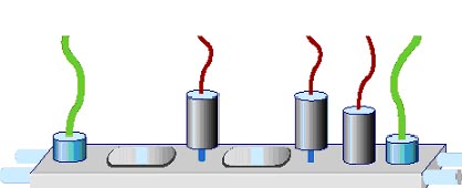
Coupling the two components together yields the first Universal Flow Stick and offers significant advantages. First, the continuous calibration further increases the range of the pressure-based real-time measurement. The resulting wide range, gas independent design reduces the number of configurations from thousands to only a few. Ordering, manufacturing and use are all made simpler and faster. Second, the continuous redundancy offers predictive maintenance capabilities. By monitoring the calibration of real-time measurement and control parameters, imminent failures are predicted and avoided. These include: flow path and filter clogging, contamination, condensation, plating effects, supply line and regulator failures, and even some single point gaging errors. Third, the simple first-principle nature of the calibration technology yields the most precise point-of-use measurement possible. Manufacturers use calibration systems that utilize the Ideal Gas Law today to calibrate Mass Flow Controllers at the factory. An important aspect of the Cyber Instruments design will utilize a unified fabrication principle. Where today individual components are connected together with vacuum-tight ultra-clean sealing technologies, the flow path of the Universal Flow Stick can be machined into a two piece base. Machined features will include: valve bodies, filter housings, calibration volumes, flow connections, and the flow element. Third-party valve actuators and gauge components will be modularly mounted. Figure 1 shows an artist rendition of the Universal Flow Stick.
This design approach eliminates the metal seals and body housings of individual components, saving significant manufacturing costs. Also, the single block design eliminates alignment and stack-up tolerances inherent in the traditional plumbed component approach. The unified fabrication principle is supported by the novel design architecture that yields the Cyber Instruments wide-range, gas-independent, Universal Flow Stick. The control electronics are configured to support the semiconductor industry's migration toward advanced process control architectures, distributed intelligent subsystems and fab-wide data access and management via SECS/GEM and TCP/IP. The latter also yields Internet access to the Cyber Instruments Universal Flow System allowing remote monitoring, diagnostics and field service support. ObjectivesThe fabrication of a complete package representative of the final product will require the effort of a multi discipline design team. It was decided that a proof of concept device should be fabricated out of commercially available pieces that represent the final and combined design. The main objective was to create a design that demonstrated that the theory was sound, and that the design could be implemented in the form of a real, working system. The following overall objectives were defined as being critical to the POC project:
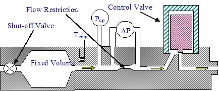
Background TheoryThe POC device was designed to demonstrate operation that is gas independent, operation over a wider range of flow than conventional thermal MFC technology, and greater accuracy of flow than current technology devices. Its design was based on equipment described in Cyber Instruments intellectual property that is currently covered by Patent 6,119,710, “Method For Wide Range Gas Flow System With Real Time Flow Measurement And Correction”. The core technology is best understood by referring to the device shown in Figure 2.
The flow control technology can be most easily understood by viewing the flow control system in two sections. Under normal flow conditions the flow of gas is controlled by the pressure based flow system in the right hand portion of Figure 2. The absolute pressure and pressure difference signal (across the flow restrictor) when compared to a desired set point, determines the position of the flow control valve. The control valve thereby adjusts the gas mass flow rate until the desired pressure difference is developed across the Flow Restrictor and the desired flow is achieved. For this section the flow can be described by:
mdot is the True
Mass Flow (SLM)
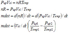
DP is differential pressure across flow restrictor Pup is upstream pressure from the flow restrictor Temp is the gas temperature Gas is a gas specific constant A target DP is calculated from the above equation after measuring Pup, and Temp and using the required flow rate and the previously calculated gas specific constant, Gas. Periodically, recalculation of Gas is accomplished by performing a calibration cycle utilizing the fixed volume in the left side of Figure 2 and a First Law of thermodynamics. This operation produces a measurement of true mass flow rate, independent of gas type, through the device. This can be expressed as:
Pup is the
pressure in the volume
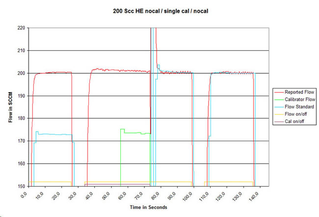
Vol is the volume size n is the number of moles of gas in the volume R is the Universal Gas Constant Temp is the temperature of the gas During the calibration operation the inlet valve to the system is closed and the gas is supplied from the known upstream fixed volume. The time rate of change of the pressure in the fixed volume and the gas temperature are measured and true mass flow rate, independent of gas type, is calculated. The parameters used for this calculation are the gas temperature, the drop in pressure in the fixed volume, and the time measured for the pressure to drop in the fixed volume. As a result of this measurement the actual flow supplied by the differential pressure flow device is corrected to give the desired flow rate by adjusting Gas based on the rate-of-fall flow measurement. The new Gas is saved and periodically adjusted to correct variations in system parameters that might affect calibration of the system. Timing diagrams demonstrating the system operation can be found in Appendix 1 of this report. Description of SystemThe system actually implemented to demonstrate the proof of concept utilized off the shelf components currently available from several manufacturers. These included pneumatic shut-off valves from Parker-Hannifin (Nupro), various plumbing fittings, a small (75 cc) calibration volume, MKS capacitance manometers, and an MKS pressure controller and control valve. In order to perform high-level system control and execute the system algorithms, we used a Data Acquisition System (DAQ) from National Instruments and programmed the system utilizing LabVIEW. This software package is very flexible and easy to program, allowing high level design and implementation without having to generate low level microprocessor code. In order to check the actual performance of our device we purchased a complete calibration system from DH Instruments. This company produces the calibration systems currently utilized by many of the thermal MFC manufacturers in their calibration labs. It is NIST traceable, and all calibration data on these devices can be made available if required. It should be stressed that the calibration standard was used as a reference only – the output of this device WAS NOT used in any way to adjust the flow from the POC device. All calibrations of the POC were self-calibration operations that were NOT tied to the flow reported by the calibration standard. A diagram of the POC system and pictures of the selected sections of hardware can be found in Appendix 2. Results of ExperimentIn order to check the operation of the POC over a small sample of gasses the POC was operated with Nitrogen, Argon and Helium. The algorithms developed to operate the system were debugged and modified only slightly from their original design. Several pieces of performance data were taken, including accuracy measurements, and the ability to calibrate true mass flow for multiple gasses. No system optimization has been performed, this topic is covered in the section entitled ‘System Improvements’. In order to check the systems ability to self calibrate and operate independent of gas type, we operated the system with the three gasses and checked its ability to self calibrate and perform normal flow operations. Figure 3 below shows the operation of the system with Helium at 200 sccm. This figure actually shows three separate flow operations. The first portion of the graph shows an uncalibrated flow, the second section shows a flow operation incorporating a self-calibration cycle, and the third section shows a normal flow operation subsequent to the self-calibration operation.
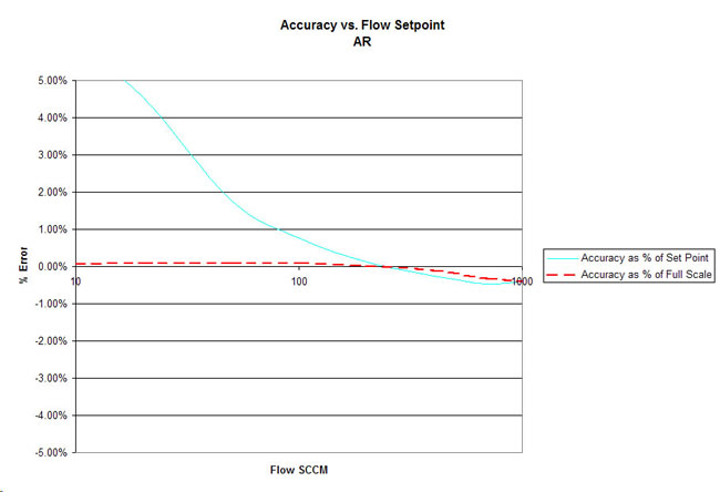
During the first flow operation it can be seen that the red line indicates that the differential pressure based flow system, not knowing what gas it was flowing, controlled at what it thought was 200 sccm. During that operation, however, the independent flow standard indicated a flow of approximately 174 sccm as shown by the blue line. During the second operation the single self-calibration cycle is performed at the beginning of the operation, and the green line indicates the true mass flow measured by the rate of fall of pressure in the fixed calibration volume. (The delay between the start of flow and the beginning of the calibration cycle was completely arbitrary.) At the completion of the calibration operation a new Gas constant is calibrated and used in controlling the differential pressure based flow system for the remainder of this chart. It can be seen that the real flow, indicated by the flow standard in the blue line now reflects the correct, desired and indicated flow of 200 sccm. Several additional similar flow operations are shown in Appendix 3. Note that the response time of the system is very fast. The response time of typical pressure transducers that are used are on the order of single millisecond time constants. The time constant of the capillary tube in a thermal mass flow controller is approximately 1 second, making this sensing technique 2 to 3 orders of magnitude faster. The system above has not been optimized for speed of response, so faster response time is expected. Also note that this graph has been plotted on an expanded scale for the Y-axis. A plot of the accuracy data for Argon appears in Figure 4. Note that the information is plotted on a logarithmic scale, and that it covers a range from 10 sccm to 1000 sccm. Conventional thermal MFC technology is typically rated for accuracy in terms of % of full scale for the device. It can be seen that the POC device, rated for operation as a percent of full scale, would perform at well below 0.5% of full scale over its entire range of operation. Rated as a % of set point device the POC performed better than 1% of set point all the way down to 10% of full scale. The other significant fact is that current thermal MFC technology can only operate from 100% of full scale down to approximately 10% of full scale, representing a turn down ration of 10:1. The POC system, in its current form, operates from 100% of scale down to 1% of full scale. This represents a turn down ration of 100:1, which is 10 times greater range than thermal based technology. We believe the range of this device can be extended further. This will be covered in the ‘System Improvements’ section as well. Accuracy data for Helium and Nitrogen can be found in Appendix 3.
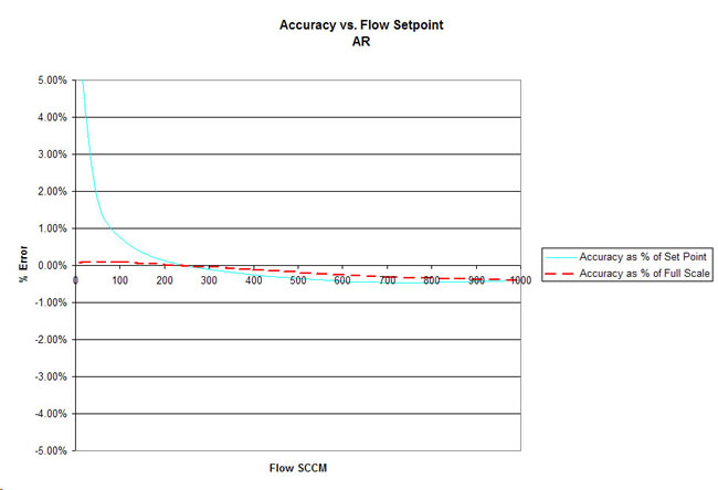
It should also be noted that the accuracy data was taken after a single point calibration at 200 sccm. No specific calibrations were performed at any of the other tested set points. This explains why the accuracy in these charts appears greatest at approximately 200 sccm. Since the normal operation of the system would be to self calibrate at each set point as the system operated in normal process conditions, the self-calibration process would generate greater accuracy as percent of set point. Cyber believes that this instrumentation should be rated for accuracy in terms of percentage of set point, which is more appropriate for an instrument that operates over a wide range of flow. The same data, plotted on a linear scale, appears in Figure 5.
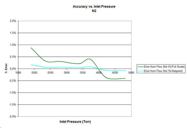
Another characteristic of current Thermal MFC technology is a sensitivity of the devices to the inlet pressure of the gas supply. Calibrations vary significantly as a function of this pressure, often dictating the inclusion of pressure regulators upstream of these devices. Not only to the regulators add substantial cost to the system, they are mechanical devices that are often a source of particulate generation. In order to test the Cyber technology for sensitivity to upstream pressure variations, two tests were run. The first test measured the accuracy of the system after a single calibration was performed on the device at 200 sccm Nitrogen. The inlet pressure was varied without recalibrating the device at each inlet pressure to test the stability of the core differential pressure flow controller. The results of that test are shown in Figure 6 below.
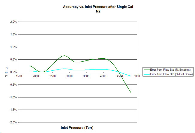
The device was then operated over the same range of inlet pressures with a single self-calibration operation performed at each pressure. The effect of adding the calibration operation can be seen in Figure 7 below. It shows that the basic device is inherently insensitive to the inlet pressure, even without performing calibrations at each specific pressure. Our ability to measure the error was limited to the resolution of the flow standard, but appears to be better than .5% of reading over the entire range. When measured in terms of thermal MFC technology specifications, the Cyber device is better than .2% of Full scale over the entire range.
System ImprovementsAlthough the performance of the POC exceeded our expectations several areas have been identified that limited the operation of this device. They are, in no particular order of importance:
ConclusionsWe believe that the POC device met the objectives of the project. The table below summarizes the performance comparisons of the current thermal based gas delivery products relative to the performance of the POC.
The algorithms developed for the POC, while functional, have not been optimized. Operation of the system continues to yield improved measurement techniques, and better logical sequences to help increase performance. The calibration cycle time, for example, can be significantly shortened by slight algorithm changes that could easily reduce the time to calibrate by 75% or more. It is important to realize that even though the system is self-calibrating, the flow of gas from the system is constant and stable, and process can be performed during the period of time that the system is calibrating itself. Many additional features will be built into the operating system that will best be constructed through some other vehicle than LabVIEW.
|
||||||||||||||||||||||||